How to Calculate the Main Motor Power for Grinding Mill Machines
Introduction
Properly calculating the main motor power for grinding mill machines is critical for ensuring optimal performance, energy efficiency, and equipment longevity. This technical guide explores key factors in power determination and introduces ZENITH’s advanced grinding solutions.
1. Fundamental Power Calculation Principles
The main motor power (P) for grinding mills can be calculated using the basic formula:
P = (Q × Wi) ÷ (η × 3600)
Where:
Q = Mill capacity (t/h)
Wi = Bond work index (kWh/t)
η = Overall efficiency factor (typically 0.6-0.8)
2. Key Influencing Factors
2.1 Material Characteristics
- Bond work index (Wi)
- Feed and product size distributions
- Moisture content and abrasiveness
2.2 Operational Parameters
- Mill rotation speed (as % of critical speed)
- Grinding media load and size distribution
- Pulp density (for wet grinding)
3. Advanced Calculation Methods
3.1 Bond’s Law Refinements
The standard Bond equation can be modified for specific mill types:
P = K × Q × (1/√P80 – 1/√F80) × C1×C2×C3
Where correction factors account for:
C1 = Dry/wet grinding
C2 = Open/closed circuit
C3 = Mill diameter effects
3.2 Specific Energy Approach
For modern vertical mills like ZENITH’s LM Series Vertical Roller Mill, specific energy consumption (SEC) provides more accurate estimates:
| Mill Type | Typical SEC Range (kWh/t) | Efficiency Factor |
|---|---|---|
| Ball Mill | 15-40 | 0.60-0.75 |
| Vertical Roller Mill | 10-25 | 0.75-0.85 |
| Ultrafine Mill (XZM Series) | 25-50 | 0.70-0.80 |
4. ZENITH’s Technical Solutions
With over 30 years of grinding technology innovation, ZENITH offers precisely engineered mills with optimized power configurations:
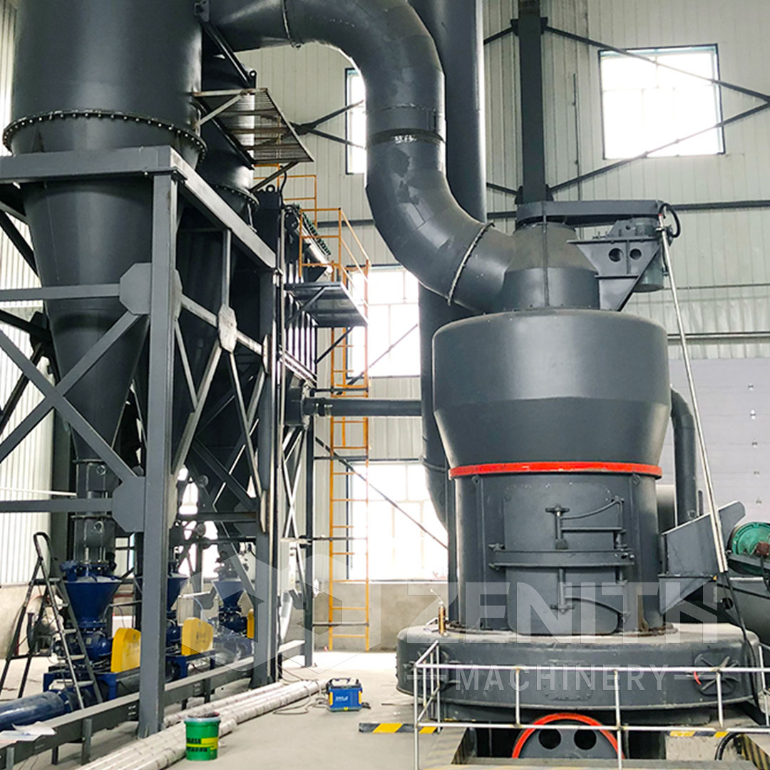
4.1 XZM Ultrafine Mill Series
Our XZM Ultrafine Mill achieves 30% energy savings through:
- Intelligent automatic feedback control
- Vertical turbine classifier system
- Special alloy grinding components
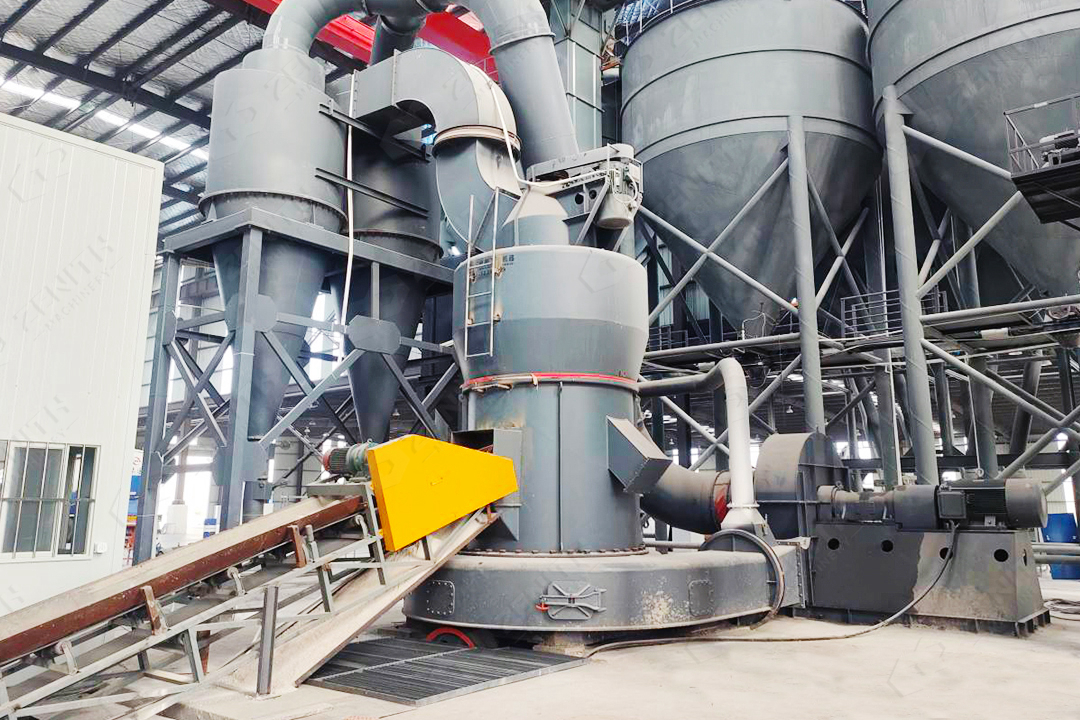
4.2 MTW Trapezium Mill Series
The MTW European Trapezium Mill features:
- 98% efficient bevel gear transmission
- Curved air duct design reducing power loss
- Wear-resistant volute structure
5. Practical Calculation Example
For a limestone grinding application requiring:
- Capacity: 15 t/h
- Feed size: 20mm (F80 = 16,000μm)
- Product size: 325 mesh (P80 = 45μm)
- Bond Wi: 12 kWh/t
Using our LM190K Vertical Roller Mill (SEC = 18 kWh/t):
P = 15 t/h × 18 kWh/t ÷ 0.82 = 329 kW
We recommend selecting the 400kW model (LM190K) to account for startup loads and potential material variations.
6. Conclusion
Accurate motor power calculation requires comprehensive consideration of material properties, operational parameters, and mill design characteristics. ZENITH’s grinding solutions incorporate these factors through:
- Pre-engineered power matching across our product range
- Energy-efficient designs verified by field installations
- Customizable configurations for special applications
Contact our engineering team for personalized power calculations and mill selection recommendations based on your specific grinding requirements.